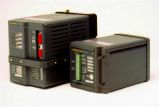
 One of the most challenging railway projects was FS2600. This was
a new track circuit to overcome compatibility problems with the new channel tunnel trains and
the existing 50Hz track circuits. The problem being that the timescales for the project were
impossibly tight.
My involvement began at the very start of the project when I produced simulations of the existing railway and tried various track circuiting ideas to derive a working frequency range. From this I developed a method to use the core of an existing track circuit. This could not involve software changes as the timescales would not allow the production of SIL4 software.
Instead the incoming signal was heterodyned down to baseband. This is a useful DSP technique as it makes sharper filters easier. The trade-off is that noise can alias in so you need a filter before heterodyning as well as the filters after. I designed all of these filters, 21 orders in total.
The front filter was a real LC ladder, but re-arranged to fail-safe principles. The post heterodyning filters were also LC ladders but with gyrators providing the inductors. The reason for taking this approach was to allow an FMEA to be performed, something that would have been problematic with a filter IC. Plus stability and second sourcing was a concern with filter ICs. The gyrators used one dual TL071 per inductor and were very stable. Changes in gyrator resistor values had very little effect on filter performance. This is not like filter ICs but it is as should be expected. LC ladders are very tolerant of component changes which is all gyrator resistor changes are at the end of the day.
The system level design is also interesting and was the subject of a paper I co-wrote for the IRSE Aspect 95 conference, and which was also presented at 2 other venues. Unlike other track circuits the set up procedure for FS2600 was mathematically proven. This is not to say the setup procedure was difficult, only two readings were required with a final measurement for a cross-check.
However the set up procedure required a calculator which was deemed not to be acceptable and the time scales did not allow for type approval etc. for a custom meter. The solution I came up with to divide the second reading by the first was an analogue calculator, a 10 turn pot. The pot was adjusted on the first reading to give a value of 1. Then the second reading could be read directly off a standard meter. As the set up box now consisted of a standard DVM and passive components then no EMI testing was required and the time scales were met.

Recent comments